
Building the Operational Structure
Practical Tools Developed for Profoto Repair Operations
During the development of the Profoto after-sales service operation, several practical tools and supporting processes were developed to solve specific repair and maintenance challenges.
These solutions were created for the Profoto project and are used when they support actual repair work. Rather than introducing technology for its own sake, each tool was developed to solve a practical problem encountered during daily operations.
Dust Removal Booth
Every Profoto product is cleaned before repair begins.
Removing dust from the inside of the product makes inspection and repair work easier while also serving as part of preventive maintenance.
Over time, dust can accumulate inside professional lighting equipment. In some situations, conductive dust may increase the risk of electrical short circuits. Removing this contamination helps reduce the risk of dust-related faults and supports the long-term maintenance of the product.
To perform this work indoors without contaminating the repair environment, AXION HUB designed and built an enclosed dust removal booth. Today, it is used as part of the standard repair workflow for every product received.
High-voltage Detection Probe
Some Profoto lighting products contain internal circuits operating at voltages exceeding 700 volts.
During fault diagnosis, engineers often need to measure high-voltage points while the product is operating. This requires accurate measurements while maintaining a safe working distance from surrounding high-voltage components.
To support this work, AXION HUB developed a dedicated high-voltage detection probe for use during diagnostic procedures.
The probe allows engineers to perform high-voltage measurements more safely and with greater control when working inside powered products. It has become one of the specialised tools used during Profoto repair work involving high-voltage circuits.
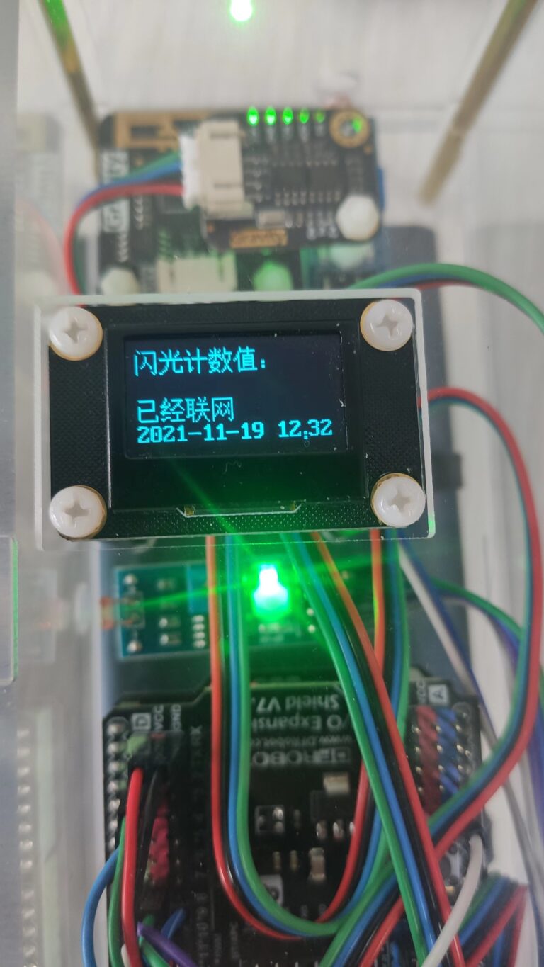
Flash Test Counter
Some repaired products require repeated flash testing after repair, particularly when the reported fault involves unstable flash output.
A verification test may require the flash unit to fire more than one hundred times. Because the flash is extremely bright, accurately counting each flash by observation alone is difficult. Engineers may also perform other work while repeatedly triggering the unit using a remote controller.
To make this process easier to manage, AXION HUB developed a dedicated flash counter that automatically records every flash.
Engineers can check the displayed count at any time and immediately know how far the verification test has progressed, making long and repetitive testing easier to complete and document accurately.
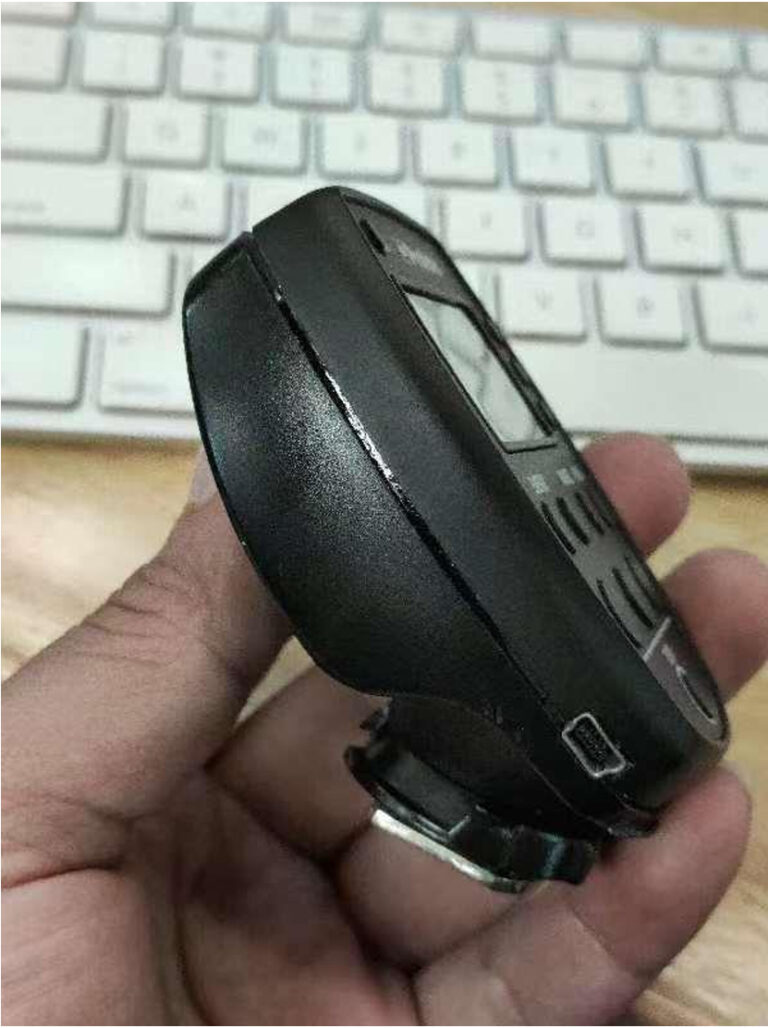
Reproducing Discontinued Parts
Some replacement parts eventually become unavailable, even though customers still require repairs.
To continue supporting these products, AXION HUB established a controlled digital reproduction workflow for selected discontinued parts.
The process begins with 3D scanning of the original component.
Rather than creating digital models ourselves, our role is to verify that the scan data is complete and suitable for further editing before it is transferred to a specialist company.
After the digital model is returned, we compare its key dimensions with the original part to confirm that the geometry has been reproduced accurately before producing the master pattern.
The verified model is then used to create a rapid master pattern with a 3D printer.
From this master, a silicone mould is produced, allowing replacement parts to be manufactured in ABS reinforced with glass fibre. When required, the final moulding process is completed by an external specialist.
Our responsibility throughout this workflow is to maintain the accuracy of the entire digital reproduction process, from the initial scan through to dimensional verification before production.
This workflow is only used when discontinued parts are no longer available and continued repair support is required.
One example involved the reproduction of replacement trigger housings for Profoto products.
A single production batch provided enough parts to support approximately two to three years of expected repair demand.
To date, these reproduced housings have been installed in more than twenty repaired products. Since their introduction, we have not received any customer complaints related to these replacement parts.
As newer product generations have become more widely adopted, demand for repairs of older products has gradually declined, making additional production unnecessary.
The same digital reproduction workflow is now also being used to develop selected tools and repair jigs for use within our own workshop.
Engineering Solutions Developed Through Daily Repair Work
The tools introduced on this page were not developed as independent research projects.
Each one originated from an actual repair requirement encountered during the operation of the Profoto after-sales service centre.
Some support everyday repair work.
Others are only used when specific technical challenges arise.
Together, they demonstrate how practical engineering, careful process control and cooperation with specialist suppliers can help maintain long-term repair support for professional products.
Continuous Technical Education